Main Controller

aerial work platform truck system

aerial work platform truck

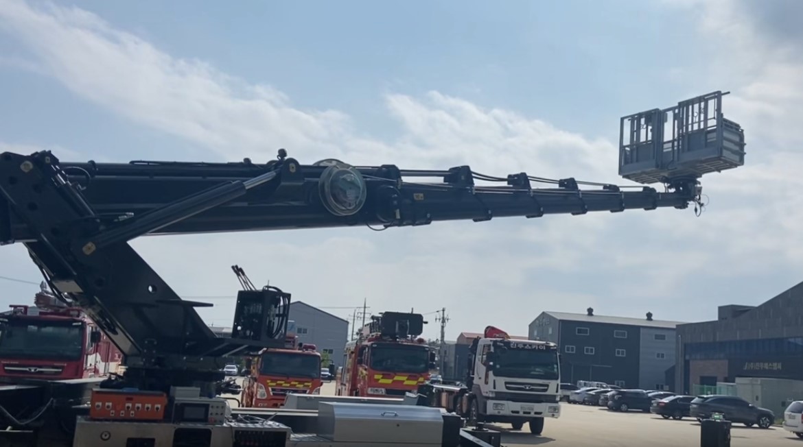
The aerial work platform is a specially designed vehicle for safe elevated operations.

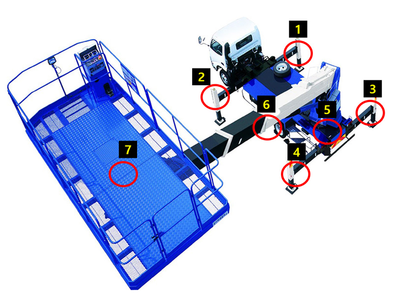
Key sensors installed to ensure the vehicle's safe functioning are as follows:

Sensors 1 to 4 consist of length sensors for stable support and proximity sensors to verify the support status. (Greater support length allows the vehicle to operate safely at higher heights.)

Sensor 5 is an encoder measuring the current angle of the platform, indicating angles on the XY plane.

Sensor 6 includes a length sensor for determining the work length and a gyroscope incline sensor for measuring angles on the XZ plane.

Sensor 7 incorporates a load cell to precisely measure the working weight. These sensors, integrated with others, calculate and control the vehicle's operations precisely, ensuring safe operations based on the vehicle's state.
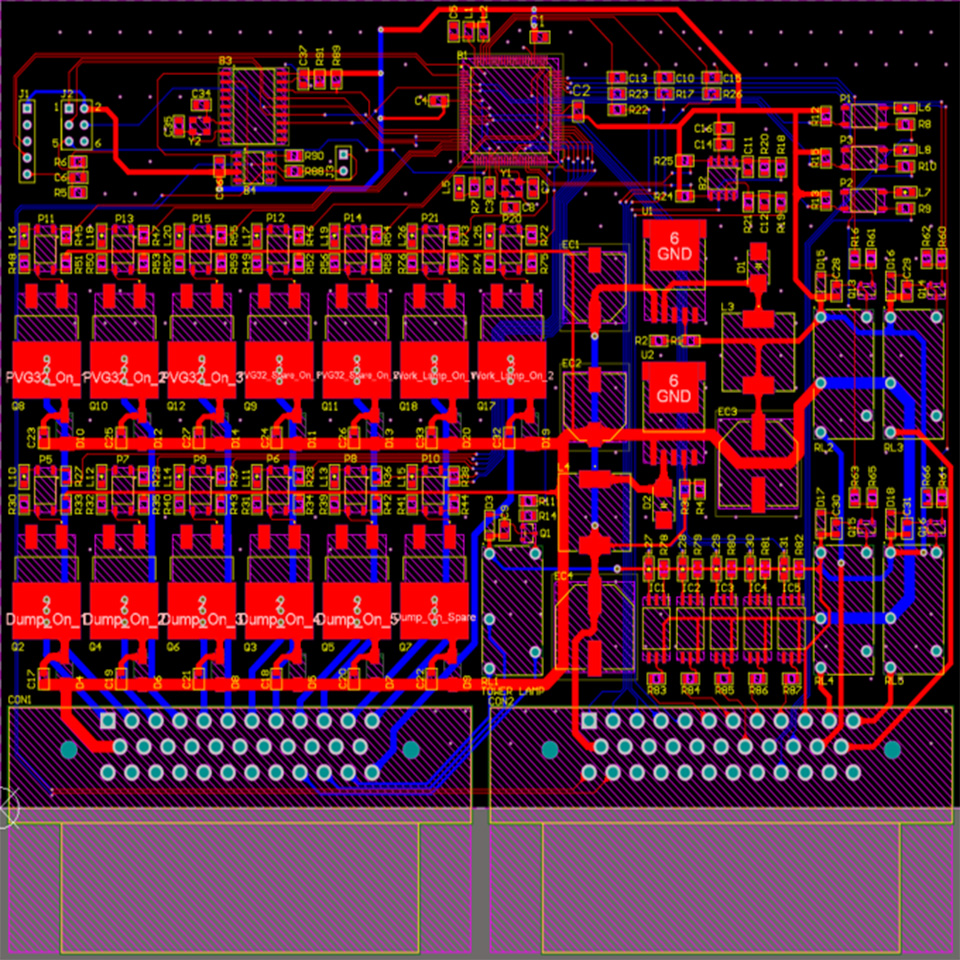
Hardware

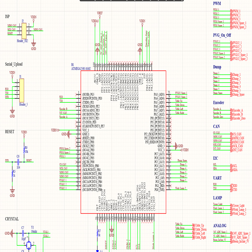
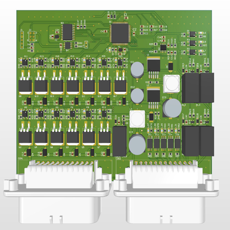
Before hardware design, I analyzed the characteristics of sensors required for the system and the features of the system controlled through PCB connections. I identified the requirements for communication protocols and interfaces such as PWM, CAN, I2C, GPIO, and USART, and incorporated them into the design.

PWM : I determined the operating voltage and frequency of the PWM ports used to control hydraulic solenoid valves.
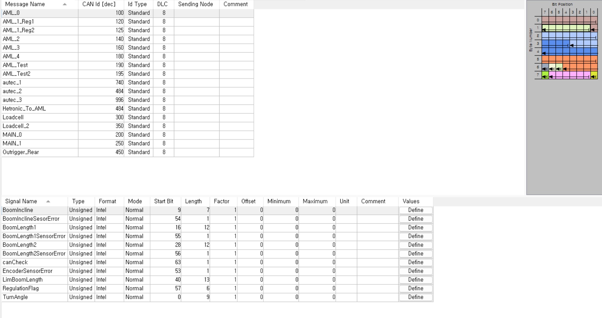
CAN : I established the CAN communication connections for data exchange with other controllers.
I2C : Utilizing I2C communication, I integrated an ADC module with 16-bit resolution.
GPIO : I ensured an adequate number of ports for sensors and external devices requiring input and output.
USART : I implemented USART ports for debugging purposes.

Additionally, I designed circuits to connect sensors such as encoders, length sensors, and angle sensors, as well as solenoid valves.

Firmware

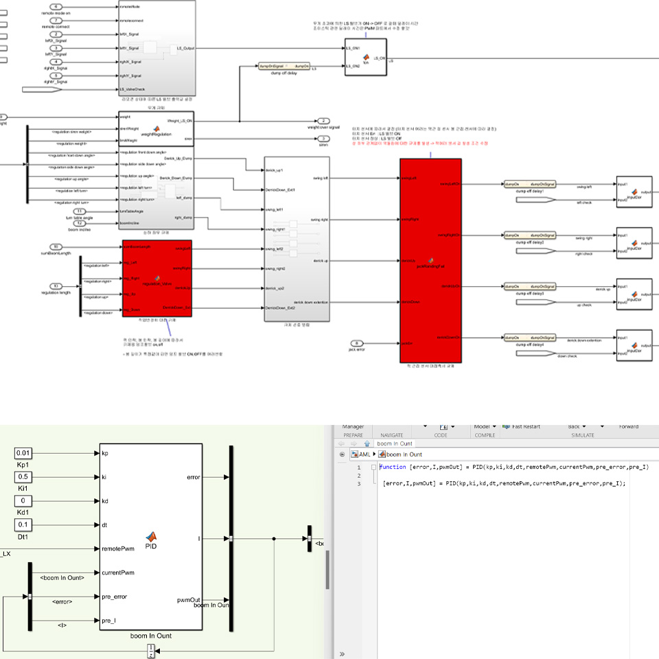
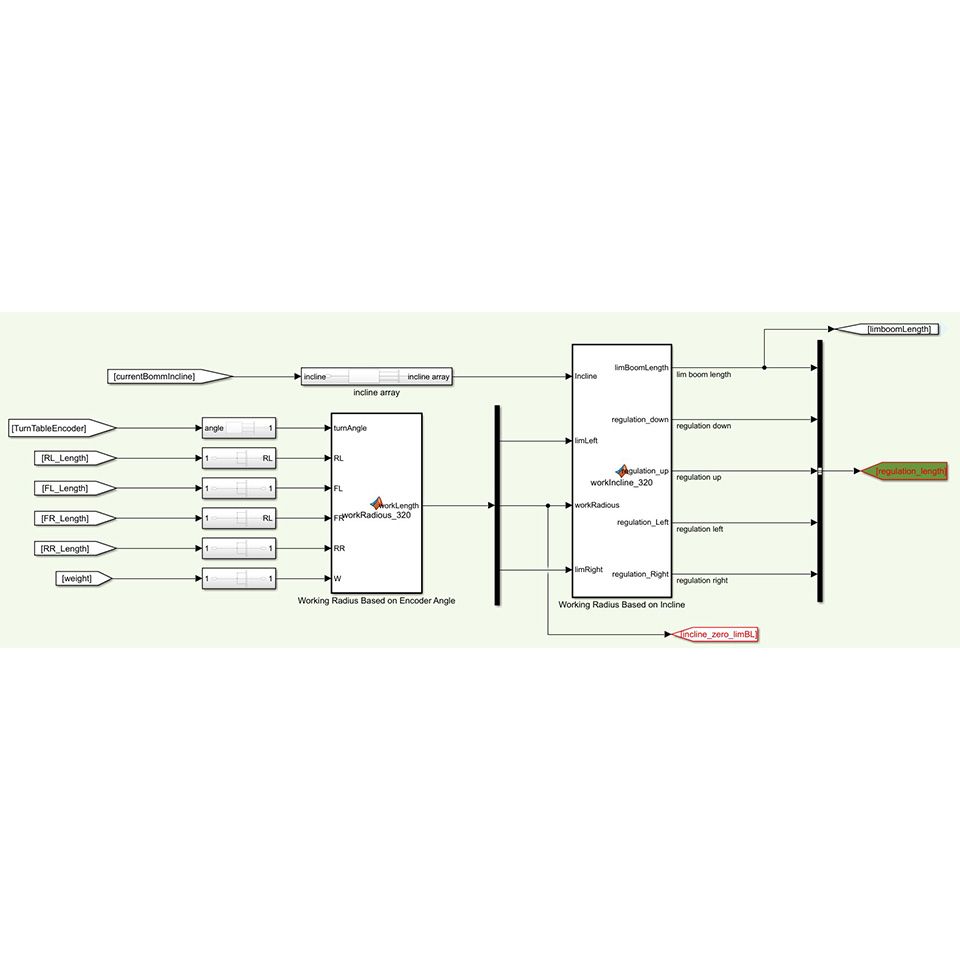
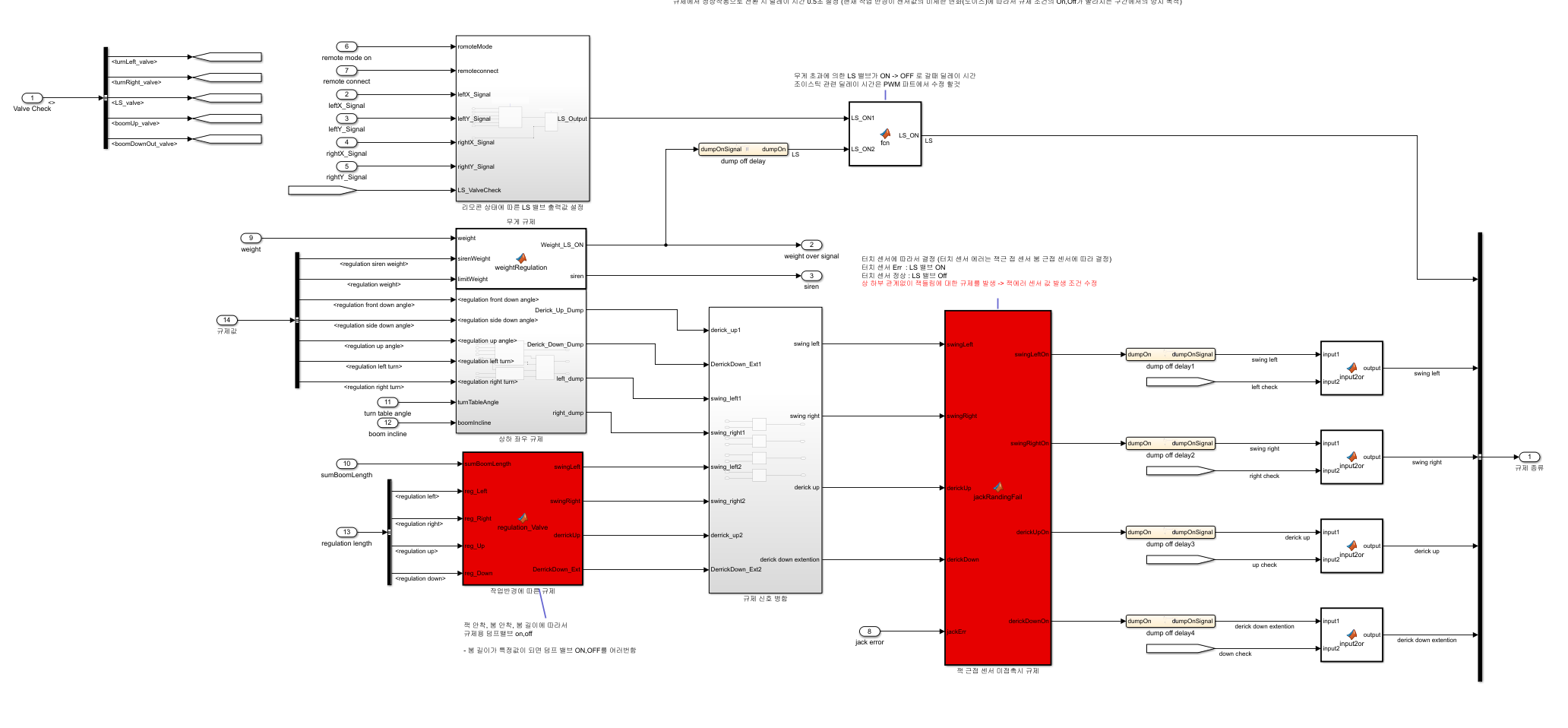
Firmware development was carried out using Simulink. Custom S-Function blocks in C language were developed for devices such as CAN, I2C, encoders, and EEPROMs as required.

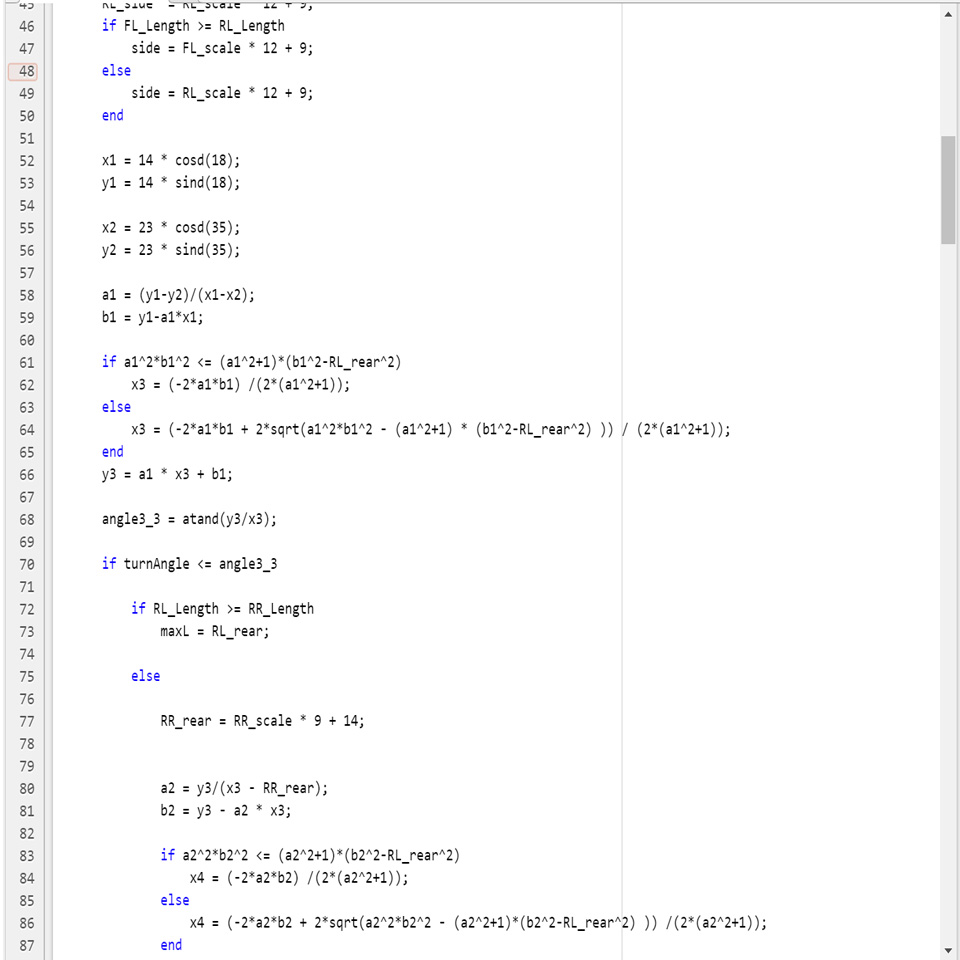
Additionally, graphs illustrating the working radius based on PID control, length, and angle were created using MATLAB M-files and integrated into Simulink blocks. Stateflow was utilized for implementing simple conditional statements.

These techniques were programmed and tested on the MCU using MATLAB and Simulink.

Introduction to Aerial Work Platform Safe Operating Range Calculation Project

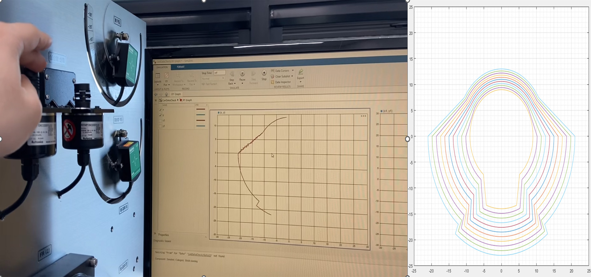
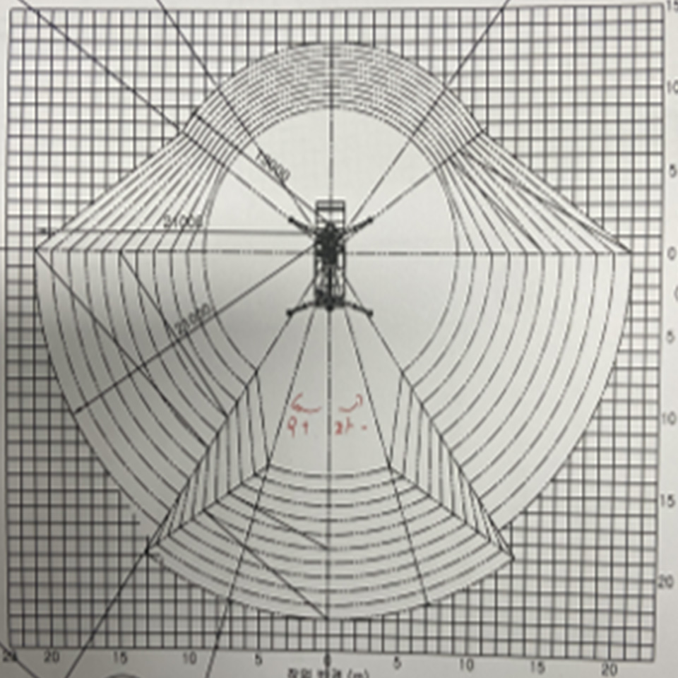
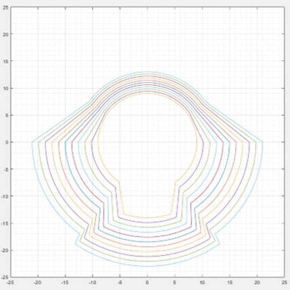
The video above illustrates the calculated safe operating range of an aerial work platform, represented graphically. The left graph depicts the work area when viewed from above, varying with the encoder's angle, while the right graph displays the lateral working length based on the encoder and angle.

These graphs are derived from real-world data obtained by testing the aerial work platform. They represent how the working environment changes concerning factors like angle, slope, length sensor values, and weight, formulated into mathematical expressions.

Uncovered in the video are the input parameters for the function used to generate these graphs. These parameters encompass weight, length sensor values, angle sensor values, slope sensor values, and the length sensor values of the vehicle's support base.

In this project, we explored methods to calculate and visually represent the safe operating range of the aerial work platform using MATLAB.

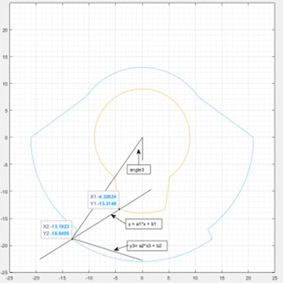
The image above illustrates the process of drawing the working radius using MATLAB.

Formulas involving trigonometric functions, equations of circles, and more were utilized. I systematically plotted graphs using MATLAB, testing various changes in sensors to observe how they impacted the working radius. This process involved analyzing the actual variations in the graph as the sensors' values changed.

Implementing Smooth Movements for Aerial Work Platforms

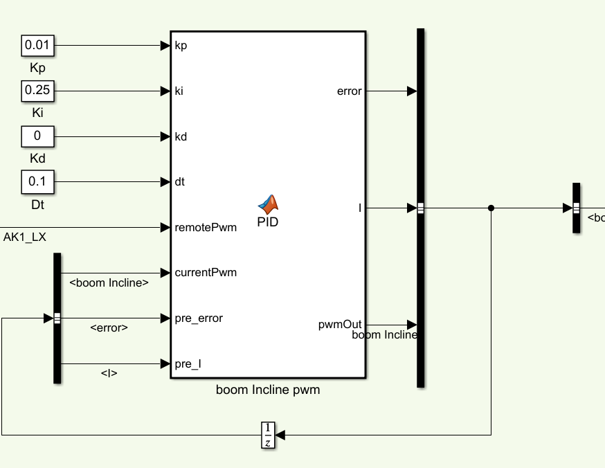
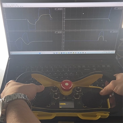
The remote control signals are processed to operate the movements of the aerial work platform. The received signals are outputted as PWM signals, and to ensure smooth movements, they are processed using PID or RAMP algorithms. The video above demonstrates the smooth input of PWM signals using the PID method.

Furthermore, to avoid jolting when extending or retracting the platform fully, a deceleration programming is implemented from one meter before the full extension or retraction point.

Smooth PWM Control for Remote Operation

PWM signals are generated based on remote control signals. Without additional processing, rapid movements of the platform can lead to hazardous operations. Therefore, PID control is applied to the PWM signals to ensure smooth movements and prevent abrupt actions.

Enhanced Safety Control Algorithms for Aerial Work Platforms

In addition, although not all detailed in the portfolio, given the paramount importance of safety, numerous control algorithms have been incorporated:

1. Unexpected Remote Control Signal Loss: Implemented actions for movements when remote control signals are unexpectedly interrupted.

2. Velocity Deceleration Before Reaching the Working Range During Platform Movement: Applied speed deceleration as the platform approaches the working range.

3. Emergency Stop Button: Integrated an emergency stop button for immediate halting of operations.

4. Speed Deceleration as Platform Extends: Programmed speed deceleration in correlation with the platform's extended length.

5. Handling Communication Disruptions in CAN Network: Developed protocols to handle communication interruptions in the CAN network.